1U Cubesat model with a reaction wheel#
Presentation#
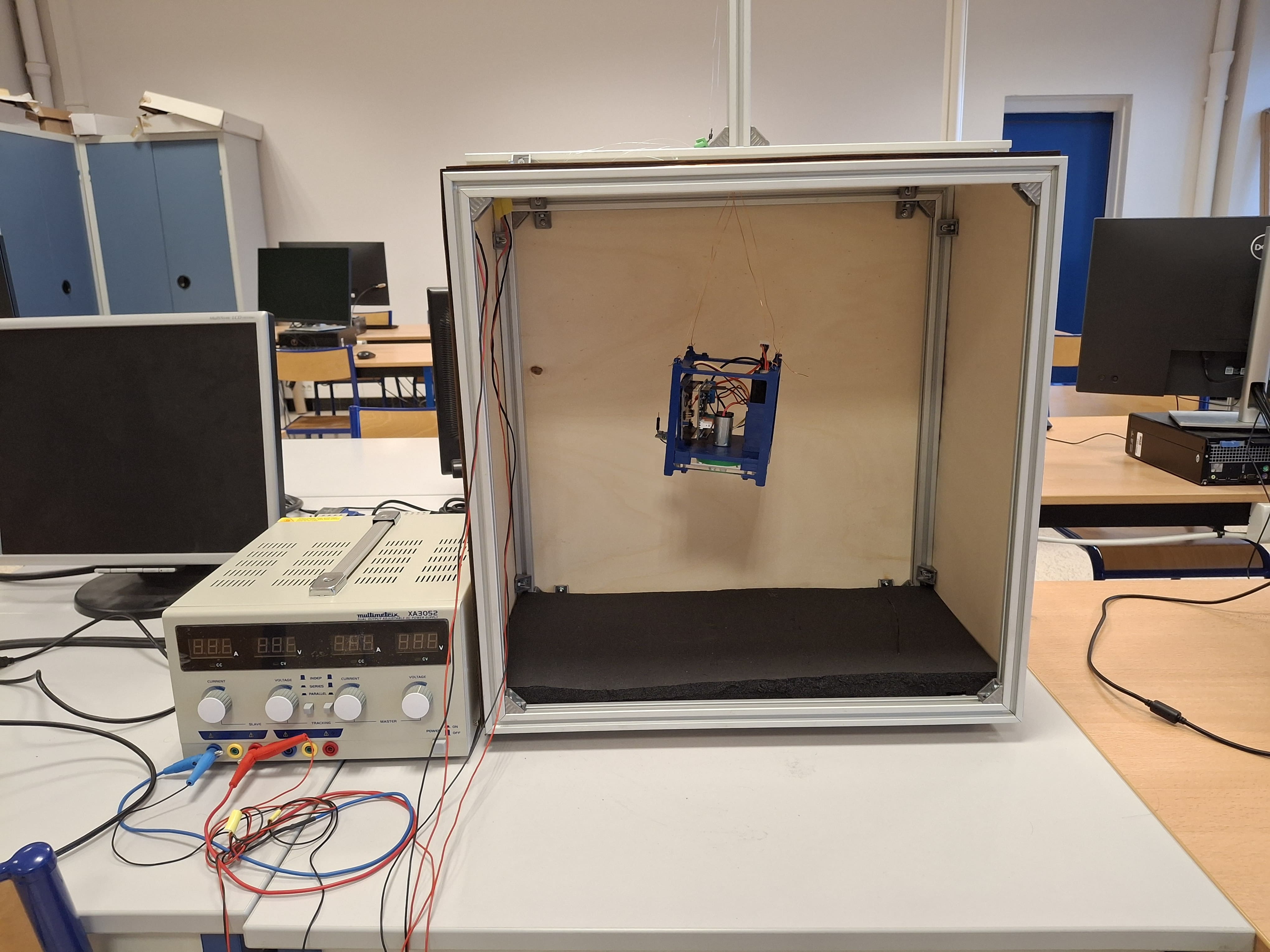
In the following image, you can see the model consisting of a Helmholtz coil, used to simulate the Earth’s magnetic field, and a CubeSat suspended from a copper wire. The purpose of this CubeSat model is to orient itself at a defined angle to the magnetic field.
At this link, you will find a video showing the desired operation of the model with :
a sensor calibration phase
an orientation phase at a desired angle
Helmholtz coil#
A Helmholtz coil consists of two identical circular coils, placed in parallel and separated by a distance equal to their radius. A current of the same intensity flows through these coils in the same direction, creating a quasi-uniform magnetic field at the center of the device.
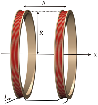
The magnetic field B at the center of the Helmholtz coil can be calculated using the formula: $\( B = \frac{\mu_0 \cdot n \cdot I \cdot R^2}{(R^2 + (\frac{d}{2})^2)^{\frac{3}{2}}} \)$
where
\(\mu_0\) is the magnetic permeability of vacuum (\(4π10^{-7}\) T-m/A),
\(n\) is the number of turns per coil,
\(I\) is the current flowing through the coils (in amperes),
\(R\) is the coil radius (in meters),
\(d\) is the distance between the two coils (equal to R for an optimal Helmholtz coil).
In our case, we have a square coil, so here’s the adapted formula:
where \(L\) is the side length of the square frames (in meters),
Voici la bobine de Helmholtz et le générateur de courant utilisés pour le TP :

The Cubesat#
The 1U cubesat is represented by a simple structure in plexyglass and ABS.
The components#
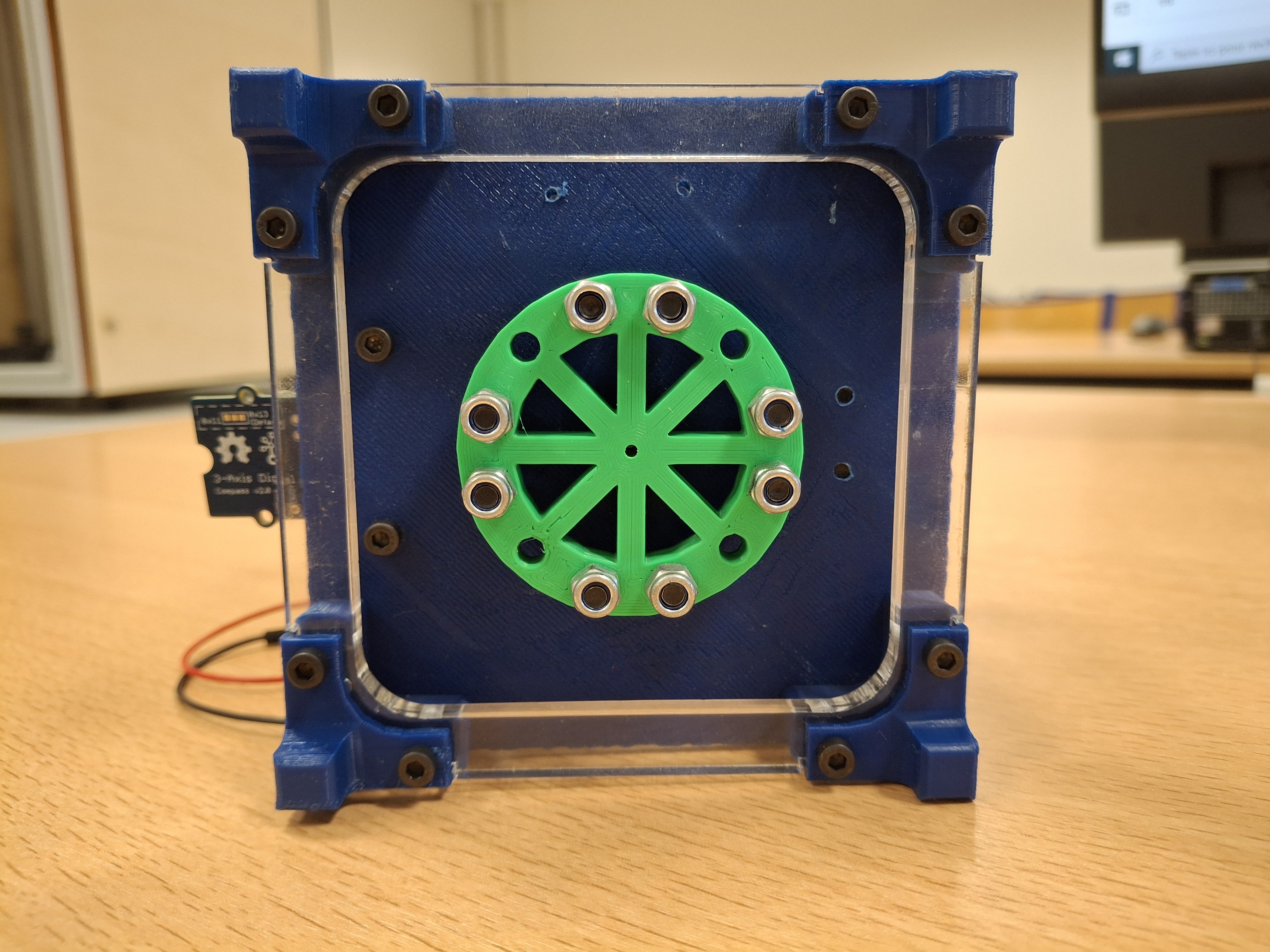
The flywheel#
A flywheel is a disc rotating around an axis fixed inside the CubeSat. It controls the satellite’s orientation, thanks to the principle of conservation of angular momentum. When the wheel is rotated in one direction, the CubeSat rotates in the opposite direction.
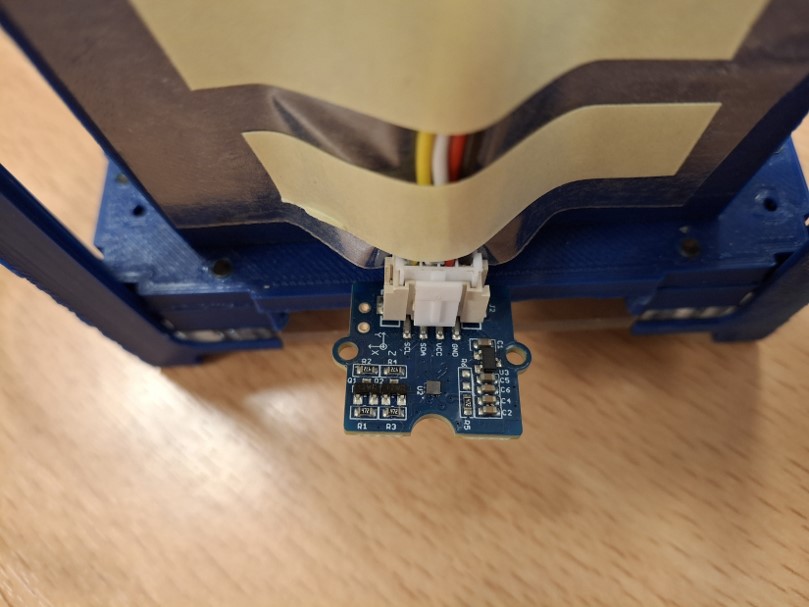
The magnetic field sensor#
This sensor measures the magnetic field of the Helmotz coil, which represents the Earth’s magnetic field. Used like a digital compass, it determines the orientation of the CubeSat in relation to the magnetic field generated by the coil.
Technical documentation: BMM150 - BOSCH
Arduino + Motor Shield#
The Arduino is the system controller. The motor shield controls the motor using PWM (Pulse Width Modulation). Here is a link to help you understand PWM.
Motor#
The direct-current (DC) motor is an electromechanical device that converts electrical energy into rotary motion (there’s a proportionality between torque and current). It’s often used in the automotive industry because of its simplicity, low cost and ease of control via a microcontroller like the Arduino.
Technical documentation: DC Motors Data Sheet
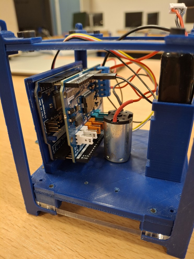
The battery#
To power the entire CubeSat, an 11.1 V LiPo battery has been added. It is directly connected to the shield, which redistributes the electricity to all other components.
Technical documention: Data sheet
The image below shows the arduino+shield, the motor and the battery:
Cubesat support#
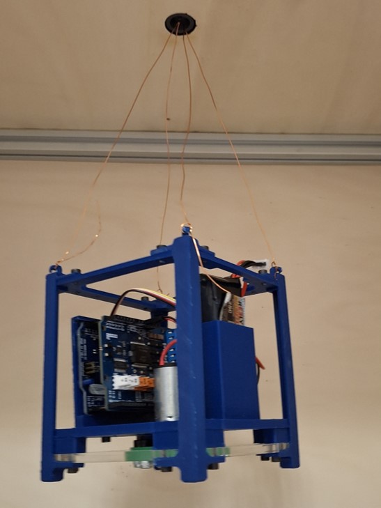
The Cubesat is suspended from copper wire, a swivel and a 3D-printed support. Here’s a picture of the support with the swivel:
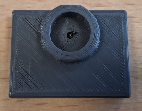
The swivel holds the CubeSat in place, allowing 360° rotation on itself with low friction torque. We’ll see later that even this low frictional torque is penalising. More advanced test solutions feature air bearings.
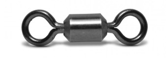
Part of the swivel is attached to a pin fixed to the support, allowing it to remain stationary. The other part of the swivel supports the copper wires used to hold the CubeSat in the air.
Wiring diagram#
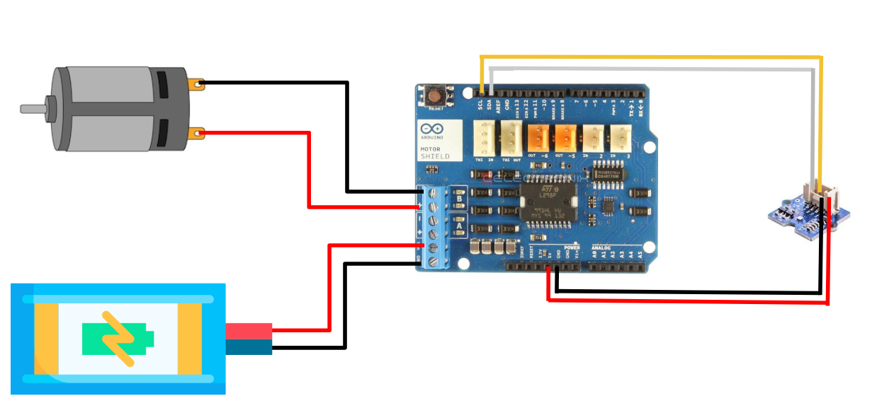
Here’s the cubesat wiring diagram:
Tips for using the model#
When using the model, set the power supply to provide a current of around 2-3 A in the Helmholtz coil.
If you wish to test your code on the Arduino, upload it, disconnect the USB cable, then connect the battery cable.
Be very careful when connecting the battery, as a wrong connection will create a short circuit and burn out the shield.