8.2. Case study and architecture presentation#
Written by Marc Budinger (INSA Toulouse), Scott Delbecq (ISAE-SUPAERO) and Félix Pollet (ISAE-SUPAERO), Toulouse, France.
This notebook aims at introducing the mechatronic system that will be studied in this Lab session.
8.2.1. Case study: the multirotor Unmanned Aerial Vehicles (UAVs)#
The multirotor concept is not new and dates back to the first works on helicopter. In the 1920s, George de Bothezat (United States, 1922) and Etienne Oehmichen (France, 1924) built helicopters with fours rotors at the end of intersecting beams. However, mechanical power transmission and control were relatively complex and bulky.
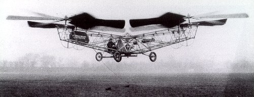
Fig. 8.1 George de Bothezat prototype#
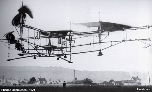
Fig. 8.2 Etienne Oehmichen prototype#
During the last decade, technological innovations have significantly contributed to the development of smart and powerful multirotor UAVs: miniaturization and microelectronic with the integration of inertial sensors, increased computational power of control processors, new battery technologies with higher energy density, permanent magnet motors with higher torque density and high power densities electric-converters. Multirotors have become a reality, and the applications are numerous: precision agriculture, inspection of power lines, transportation of goods and medical supplies, etc. This aerial vehicle concept is found in a wide range of sizes and weights, allowing the transport of payloads from a few hundred grams to hundreds of kilograms.
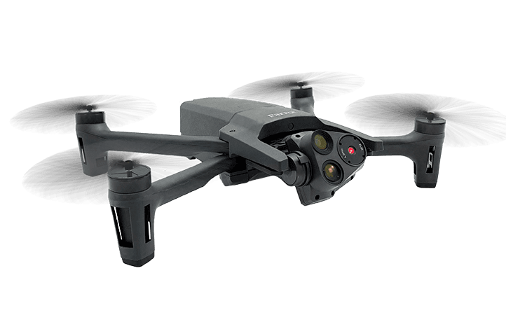
Fig. 8.3 Parrot ANAFI USA#
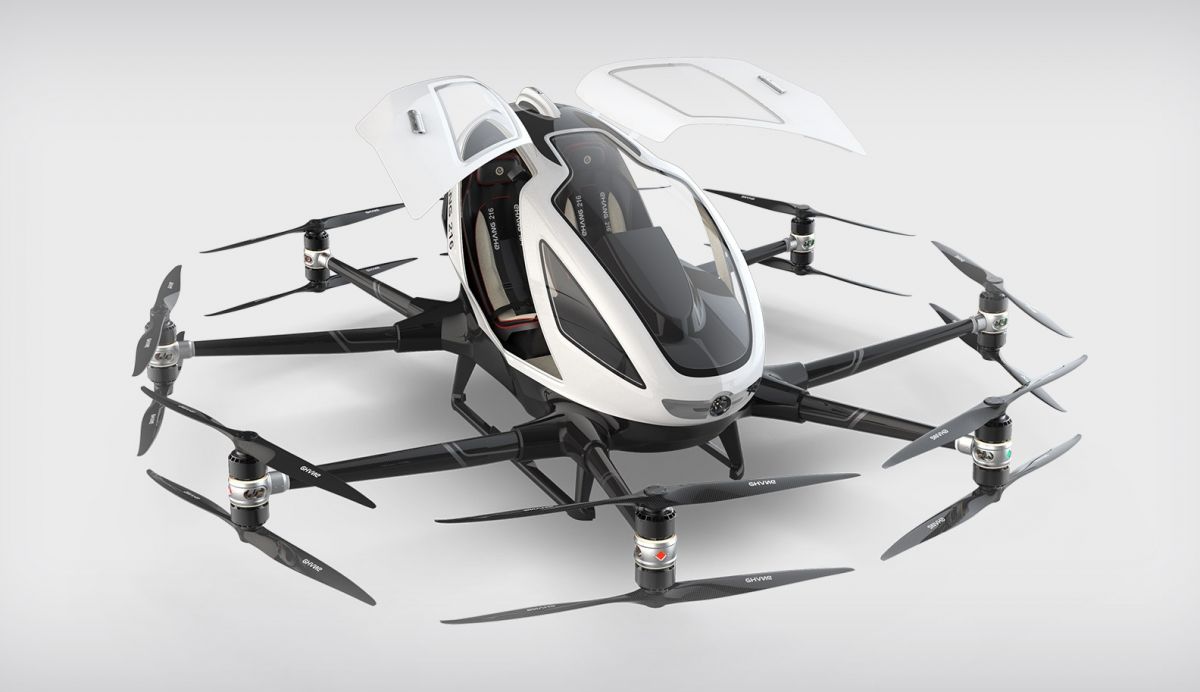
Fig. 8.4 eHang 216#
For those interested, you can find here an introduction to the history of Unmanned Aerial Vehicles, the features of quadcopters and their applications.
8.2.2. Architecture of multirotor UAVs#
Multirotor UAVs can be defined as mechatronic systems since they include a combination of mechanical, electrical and electronic disciplines.
The diagram of the drone components and the listing of drone component parts presented below comes from an article called anatomy of a drone by MakeZine. The main components are:
A. STANDARD PROP: The same “tractor” propeller used on standard front-engine R/C airplanes.
B. “PUSHER” PROP: These contra-rotating props exactly cancel out motor torques during stationary level flight. Opposite pitch gives downdraft.
C. MOTOR: Usually a brushless electric “outrunner” type, which is more efficient, more reliable, and quieter than a brushed motor.
D. MOTOR MOUNT: Sometimes built into combination fittings with landing struts.
E. LANDING GEAR: Designs that need high ground clearance may adopt helicopter-style skids mounted directly to the body, while designs with no hanging payload may omit landing gear altogether.
F. BOOM: Shorter booms increase maneuverability, while longer booms increase stability. Booms must be tough to hold up in a crash while interfering with prop downdraft as little as possible.
G. MAIN BODY: Central “hub” from which booms radiate like spokes on a wheel. Houses battery, avionics, cameras, and sensors.
H. ELECTRONIC SPEED CONTROLLER (ESC): Converts DC battery power into 3-phase AC for driving brushless motors.
I. FLIGHT CONTROLLER: Interprets input from receiver, GPS module, battery monitor, and onboard sensors. Regulates motor speeds, via ESCs, to provide steering, as well as triggering cameras or other payloads. Controls autopilot and other autonomous functions.
J. GPS MODULE: Often combines GPS receiver and magnetometer to provide latitude, longitude, elevation, and compass heading from a single device.
K. RECEIVER: Often a standard R/C radio receiver unit. The minimum number of channels needed to control a quad is 4, but 5 is usually recommended.
L. ANTENNA: Depending on your receiver, may be a loose wire whip or helical “rubber ducky” type.
M. BATTERY: Lithium polymer (LiPo) batteries offer the best combination of energy density, power density, and lifetime on the market.
N. BATTERY MONITOR: Provides in-flight power level monitoring to flight controller.
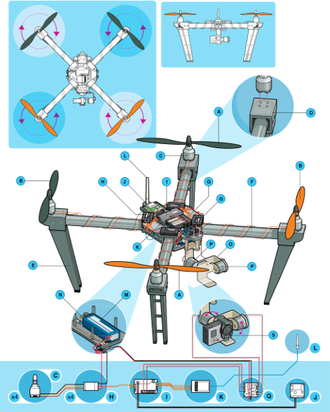
Fig. 8.5 Anatomy of a drone#
The load is often a camera system:
O. GIMBAL: Pivoting mount that rotates about 1, 2, or 3 axes to provide stabilization and pointing of cameras or other sensors.
P. GIMBAL MOTOR: Brushless DC motors can be used for direct-drive angular positioning, too, which requires specially-wound coils and dedicated control circuitry that have only recently become commercially available.
Q. GIMBAL CONTROLLER: Allows control of direct-drive brushless gimbal motors as if they were standard hobby servos.
R. CAMERA: GoPro or other compact HD video unit with onboard storage. Real-time streaming is possible with special equipment.
8.2.3. High speed Drones#
High-speed drones are designed for performance, agility : -Top Speeds: High-speed drones can exceed 100 mph (160 km/h), with some military or experimental models reaching 200+ mph (320+ km/h). -Acceleration: Rapid acceleration and deceleration capabilities, crucial for racing and evasive maneuvers. -Aerodynamics: Streamlined, lightweight frames (often carbon fiber) to reduce drag and improve speed.

High-speed drones are desgine for specialized applications:
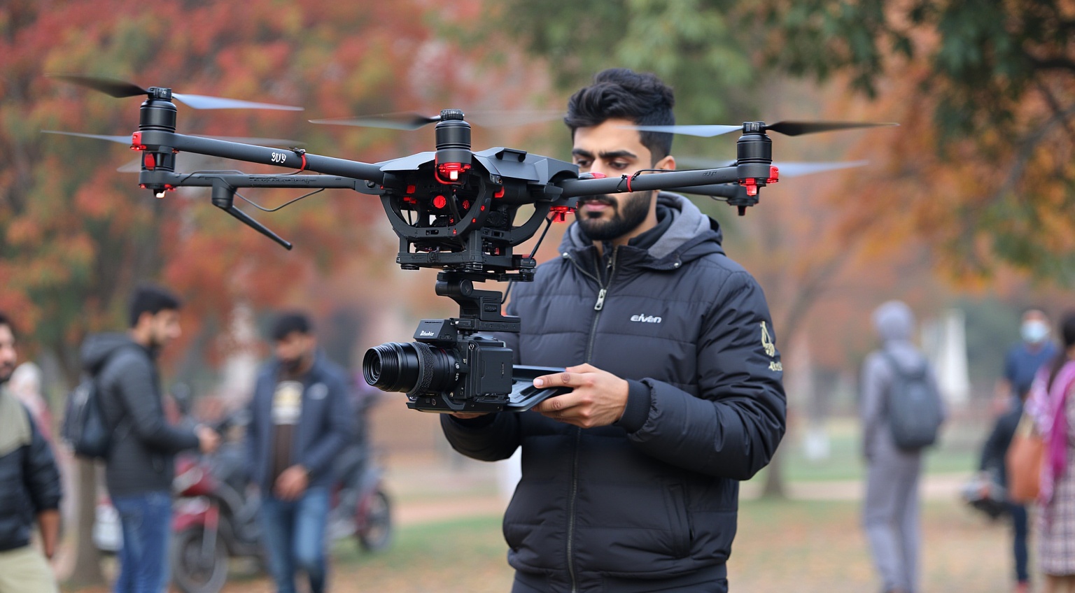
Media and Filmmaking: High-speed drones have transformed filmmaking and media production. Their agility allows for smoother transitions and precise aerial maneuvers. Drones with greater speed create immersive, thrilling perspectives.
In the early phases of the 2000s when DJI, Parrot, and Yuneec started to produce small, lightweight drones with cameras
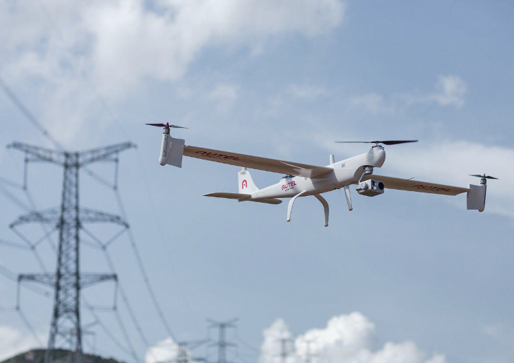
Defense and Surveillance: Defense and surveillance rely heavily on drone speed. Fast drones can track moving targets, conduct reconnaissance, and relay intelligence almost instantly.
The Sting drone can reach speeds of over 160 km/h (100 mph) and operate at altitudes up to 3,000 meters (10,000 feet)

The Dragonfish drone from Autel Robotics is a professional VTOL (vertical takeoff and landing) fixed-wing drone designed for surveillance, reconnaissance, and intelligence missions.
Healthcare: High-speed drones dramatically reduce transportation times compared to road vehicles. This speed ensures that lifesaving supplies arrive when they are needed. These drones improve survival rates in trauma situations.
[Zipline](https://en.wikipedia.org/wiki/Zipline_(drone_delivery_company) drones deliver blood products, vaccines, and medical supplies

8.2.4. Indicative project schedule#
Your goal will be to work in project groups of 4-5 students. Project groups must be compatible with tutorial and practical work groups.
Once the group has been defined:
Choose an application that motivates you: surveillance, mapping, interception, medical, etc.
Define the typical specifications of the requirements document.
Define a drone architecture that is compatible with your application and the usage scenarios that will determine the size of its components.
Be reasonable in the number of components and scenarios to be represented.
Here is an indicative schedule to follow for the supervised sessions:
1h15 TD - Definition of Scenarios, XDSM & Global Algebraic Loop, Task Distribution
2h30 TD - Implementation of equations for each component (simulation, evaluation, estimation), validation of equations on a known case study.
2h30 TD - Coordination of inputs/outputs from different teams, computer implementation of code
2h45 TP - Global Optimization & Validation on a Simple Case
2h45 TP - Interface Improvements (Data Outputs, Diagrams) & Case Study Analysis
You will be evaluated on:
Your work during the project
Your optimization code
Your oral presentation