2.1. Scenarios and Design Drivers#
2.1.1. Introduction#
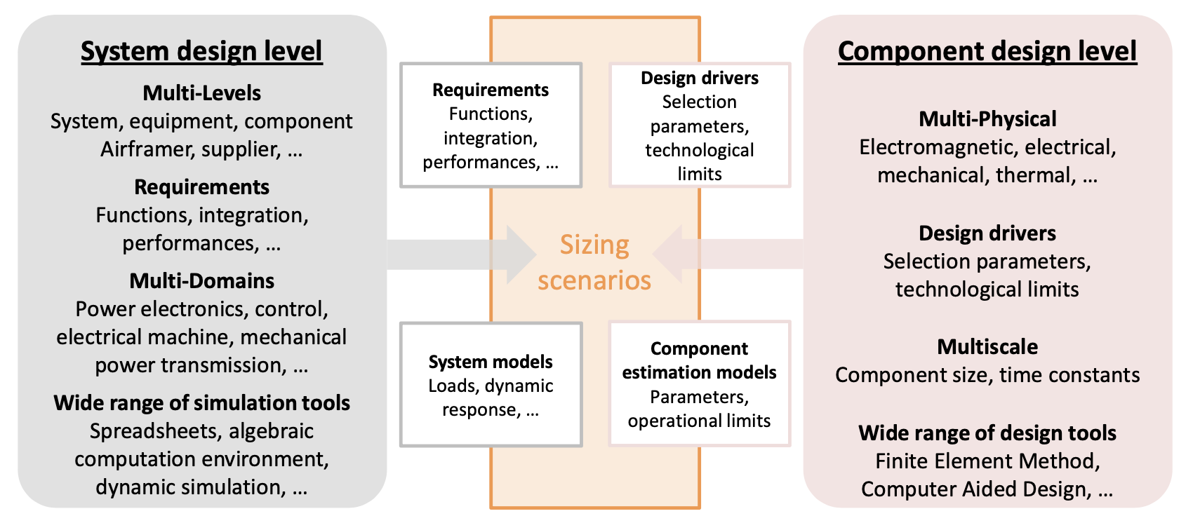
After analysing the architecture of the system to be sized, the next step is to establish the *sizing scenarios which :
represent realistic system operations: the concept of operations or a functional analysis can help you with this
risk to degrade the different components: the rest of this section will list the main design drivers for mechatronic components.
The sizing scenarios must therefore respond to a dual point of view: system/functional and component/technological. Ultimately, these scenarios could be expressed in the form of a set of operational points (e.g. Torque, Speed) or mission profiles (variable function of time).
In order to establish the main design or selection criteria for a component, it may be relevant to answer the following questions:
What are the operational limits or degradations that can occur rapidly (e.g. transiently over an operating cycle) ?
This question focuses on transient power requirements and performance → Prevents rapid damage (e.g. permanent deformation, rupture)
What losses in performance or gradual degradation can be expected during long-term continuous operation or after numerous operating cycles ?
This question focuses on continuous power demand and endurance → Addresses gradual degradation (e.g., fatigue) and ensures reliable operation during service lifetime
What imperfections can be expected in the component, e.g. in terms of stored energy (inertia, stiffness) or in terms of losses (efficiency) ?
This question focuses on compenent imperfections that
increase stresses on themselves (e.g , inertia) or on other components (e.g, efficiency)
can create new critical cases (e.g, inertia and jamming) → Induced new design drivers
2.1.2. Design drivers of main mechatronic technologies#
2.1.2.1. Architecture exemples#
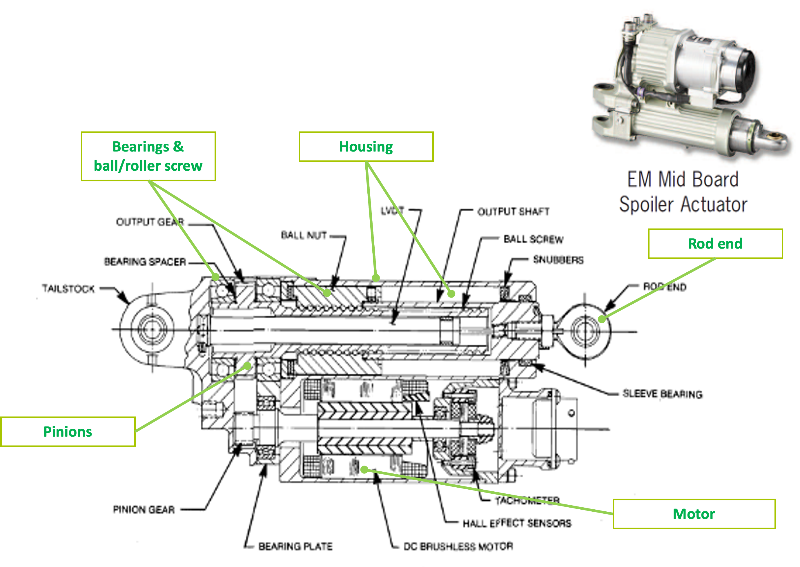
The fowolling Figure represents an EMA (ElectroMechanical Actuator) for the Boeing 787’s spoiler designed and manufactured by MOOG. It is composed of:
mechanical components for effort transmision: rod end, rod, housing
mechanical components for power transmision: ball screw, bearing, gear
electro-mechanical components such as a brushless motor
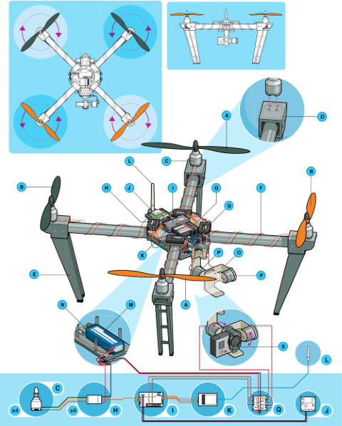
The following diagram shows the anatomy of a multi-rotor UAV. It also includes components from mechanical (propellers, arms, landing gear), electrical (brushless motor, ESC) and electronic (inertial sensors, camera) technologies.
We will now give a quick overview of the main design constraints for these families of components.
2.1.2.2. Mechanical components#
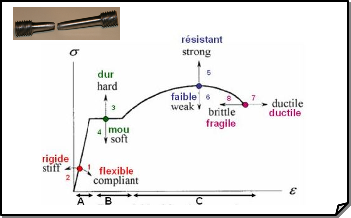
2.1.2.2.1. Maximum stress and fatigue#
Mechanical materials display linear elastic behavior (A), defined by a linear stress-strain relationship. Beyond this linear region, for ductile materials, such as steel, deformations are plastic. For many applications, plastic deformation is unacceptable, and is used as the design limitation.
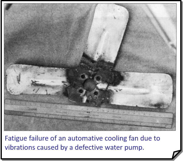
Formation of microcracks resulting from repeated mechanical stress. The cracks propagate along lines of weakness, which act as stress contractors. Fatigue is often computed for rolling elements using mission profiles that represent repetitive requests.
2.1.2.2.2. Vibration and shock#
Vibration and shocks can cause : fracture due to fatigue or mechanical overstress, wear, lossening of fasteners (e.g. screw, bolts), leaks in hydraulic or pneumatic systems due to wear or lossening of seals or connectors., accoustic noise (10-10 000 Hz).
2.1.2.2.3. Mechanical losses & Friction#
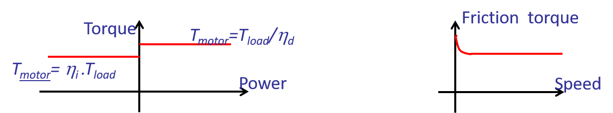
During sizing it is important to take into account the main parasitic aspect of components in terms of power transmission. For mechanical components efficiency and friction are important:
First level of modeling : constant efficiency (direct and inverse) with speed and torque.
Second level : friction increases at low speed.
2.1.2.3. Electrical components#
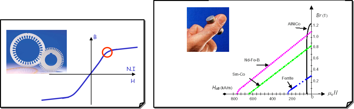
2.1.2.3.1. Saturation and demagnetization#
The magnetic fields in components such as motors, transformers and inductors are limited by the saturation limits of the magnetic materials used. Above certain currents, this saturation limits the performance that can be achieved. It is therefore advisable to operate these components below this saturation current.
Too high current can also demagnetise the materials used to make the permanent magnets.
2.1.2.3.2. Thermal failures#
Electrical energy generates heat (copper and iron losses) and increases the temperature, particularly in the winding. Several phenomena are therefore to be feared:
Drift in the values of component parameters such as resistance: increase with temperature and risk of thermal runaway depending on the drive mode.
Loss of magnetism: The Curie temperature (Tc), or Curie point, is the temperature at which a ferromagnetic or ferrimagnetic material becomes paramagnetic when heated; the effect is reversible. A magnet loses its remanent induction if it is heated above the Curie temperature.
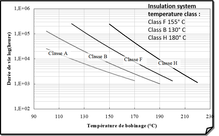
Premature ageing: Wire coils (e.g. inductors, solenoids, transformers, motors) can lose their insulation over time if operating temperatures are too high.
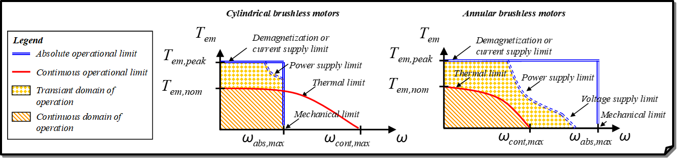
2.1.2.3.3. Brushless motor example#
The brushless electric motor provides a good illustration of these different concepts in its operating modes:
Transient operation
Limitation of the instantaneous torque to avoid a current that saturates the laminations.
maximum instantaneous speed
Continuous operation
Average Joule losses and therefore a limited average torque to avoid excessive heating of the windings and reduced life.
for certain motors with a large number of poles, a reduced average speed to avoid excessive iron losses.
In addition to these operational limitations, there are other imperfections such as:
Rotor inertia which increases electromagnetic torque for high dynamic application (e.g., TVC) or increases mechanical stress when jamming or urgency stop.
Losses, which already affect the performance of the motor itself, but also place additional issues on the components upstream of the power chain (e.g. inverter, battery) or on the cooling devices (e.g. housing for frameless motor).