8.3. Sizing scenarios and design drivers (student version)#
Written by Marc Budinger (INSA Toulouse), Scott Delbecq (ISAE-SUPAERO) and Félix Pollet (ISAE-SUPAERO), Toulouse, France.
The preliminary sizing of UAVs aims at defining the main drone characteristics and selecting the components based on a few sizing scenarios. The sizing scenarios are part of the specification process and may include both transient and endurance criteria, such as maximum rate of climb and hover flight endurance. The final overall design has to consider simultaneously the various sizing scenarios that may impact the components selection through design drivers.
8.3.1. Design drivers#
Design drivers are physical factors that influence the design process of a component. For example, the propeller design is driven, among others, by the maximum thrust it can provide.
Table 1 summarizes the main system components.
Exercise 8.1
For each component, list the main design drivers to be taken into account for the design process. Complete Table 1.
8.3.2. Sizing scenarios#
Endurance scenarios, like hover flight need to be taken into account for the selection of the battery endurance and the evaluation of the motor temperature rise. Extreme performance criteria, such as maximum transitory acceleration or maximum rate of climb are fundamental to determine the maximum rotational speed, maximum propeller torque, Electronic Speed Controller (ESC) corner power, battery voltage and power, and mechanical stress.
Exercise 8.2
For each design driver, list the critical scenarios that need to be taken into account for the component selection. Complete Table 1.
Components |
Design drivers |
Sizing scenarios |
|---|---|---|
Propeller |
Max thrust |
Takeoff |
Climb |
||
Motor |
||
Electronic Speed Controller |
||
Battery |
||
Frame |
||
Exercise: Complete the table above based on your drone application and concept. Try to limit the scenarios to be considered to two main ones. For example, for a multi-rotor drone used mainly for static observation, only hovering (endurance) and takeoff scenarios (performance) will be addressed.
8.3.3. Global sizing procedure with XDSM representation#
The following diagram represents the XDSM graph of the global sizing process of the multi-rotor. The equations representing the drone usage scenarios will be included in the overall sizing procedure. For each component or sub-part of the drone, try to determine the information flows required for these calculations.
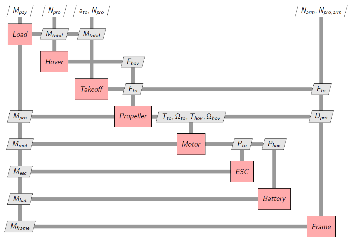
Fig. 8.6 Multirotor sizing XDSM diagram#
Exercise 8.3
Give the main sizing problems you are able to detect.
Propose one or multiple solutions (which can request equation manipulation, addition of design variables, addition of constraints)
8.3.3.1. Solution using the Normalized Variable Hybrid formulation#
The following diagram represents the XDSM graph of the global sizing process of the multi-rotor with the NVH formulation to achieve the MultiDisciplinary Analysis (MDA).
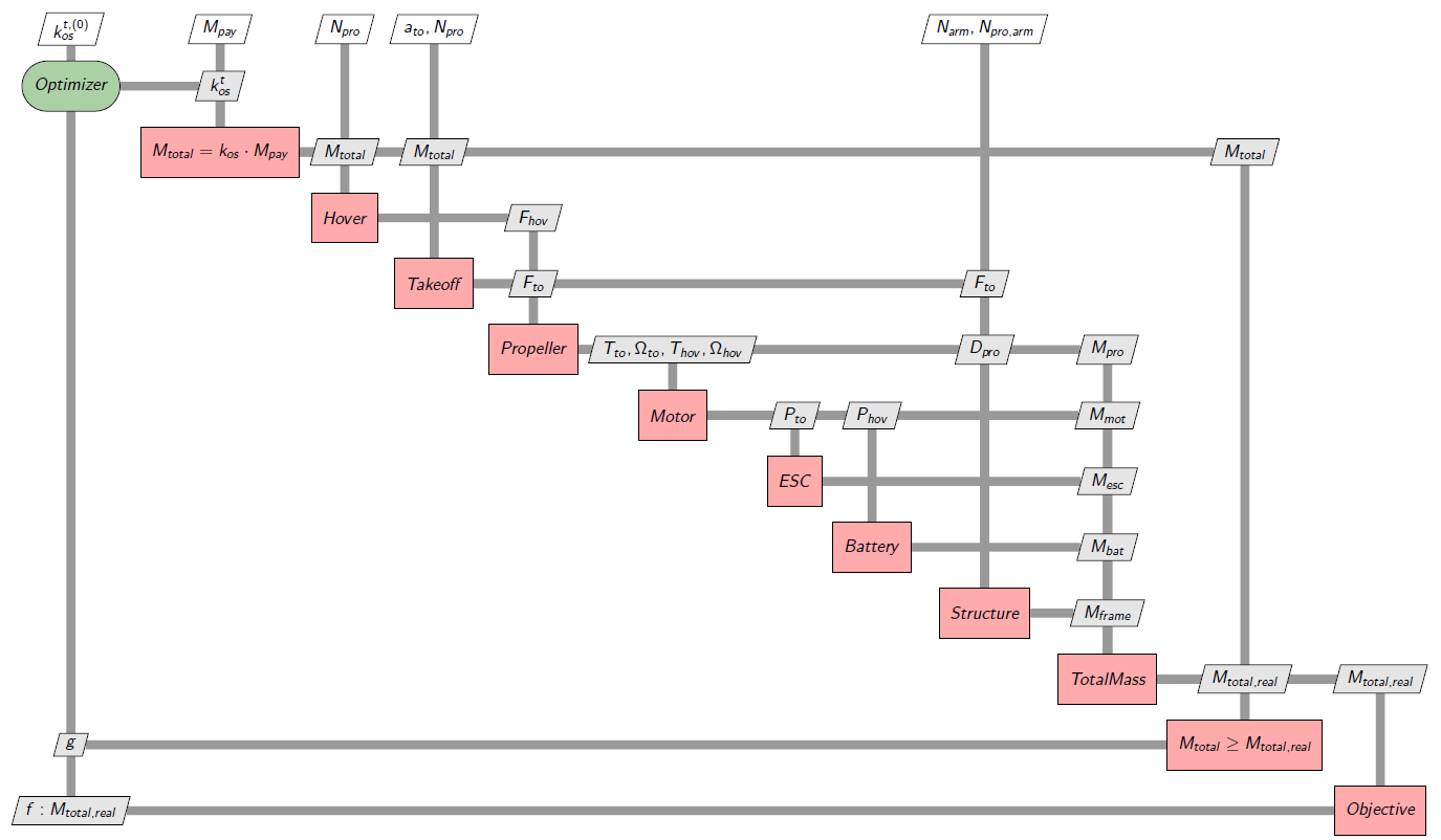
Fig. 8.7 Multirotor sizing MDA XDSM diagram#
It consists in addition an oversizing coefficent \(k_{os} \quad [1-10]\) as a design variable and additional inequality constraint \(M_{total} \geq M_{total,real}\). This way, we make sure that the drone is capable of lifting the load and itself. As we are minimizing the total mass \(M_{total,real}\) the oversizing coefficient \(k_{os}\) will tend to be as small as possible and thus the inequality constraint will be equivalent to an equality constraint (\(M_{total} = M_{total,real}\)). This is one way of solving an algebraic loop, other methods use numerical solvers or other optimizer-based formulations. The formulation of the optimization problem is the following:
The quadrotor sizing problem contains other solvability issues such as overconstrained singularities. Try to utilize the NVH formulation to solve them.
8.3.3.1.1. Main problems to be solved#
In general, the establishment of a sizing procedure involves the resolution of the following 3 problems:
a set of equations sub-constrained by the addition of a design variable in the optimization problem;
an over-constrained variable by adding a design variable (multiplier) and the transfer of the excess equation(s) in the constrained part of the optimization problem;
an algebraic loop by the use of a simplified equation weighted by a multiplying coefficient and a constraint representing the initial equation.
8.3.3.1.2. Caution for the optimizer#
Where possible:
the design variables must take the form of a normalized variable around 1 (oversize coef. for example) or easily bounded to facilitate the work of the optimizer.
the constraints must take the form of inequality and not of equality which often introduce numerical difficulties. The optimization of the objective (for example the total mass) will certainly force some (active) constraints to come to an end.