1.1. Objectives and ressources#
1.1.1. Mechatronics: multi-domain systems#
Description
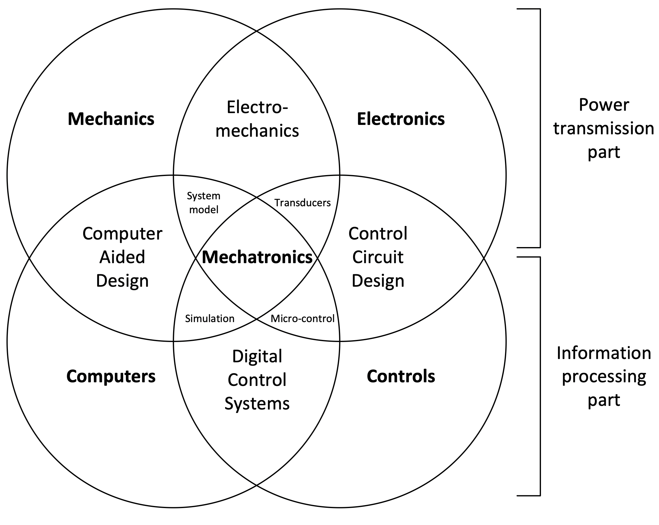
Mechatronic systems are multi-domain because they integrate mechanical, electrical, computer science, and control engineering principles:
Mechanical Domain:
Involves the physical components like structure, materials, and mechanisms.
Example: In a robotic arm, joints, links, and the end-effector are part of the mechanical domain.
Electrical Domain:
Includes electrical components such as sensors, actuators, and power supplies.
Example: Sensors detect the position of the robotic arm, and electric motors act as actuators driving the joints.
Computer Science/Information Technology Domain:
Relies on computer systems for control and decision-making.
Example: A computer processes sensor data, executes control algorithms, and makes decisions for the robotic arm.
Control Engineering Domain:
Concerned with designing algorithms and systems to control the mechatronic system.
Example: Control engineering principles are applied to ensure the robotic arm moves accurately and responds to changes.
The integration of these domains allows mechatronic systems to achieve versatility and capability through the synergy of mechanical, electrical, computer science, and control engineering principles. In return for these opportunities, design complexity can be significant.
1.1.2. Mechatronics: multi-level systems#
Description
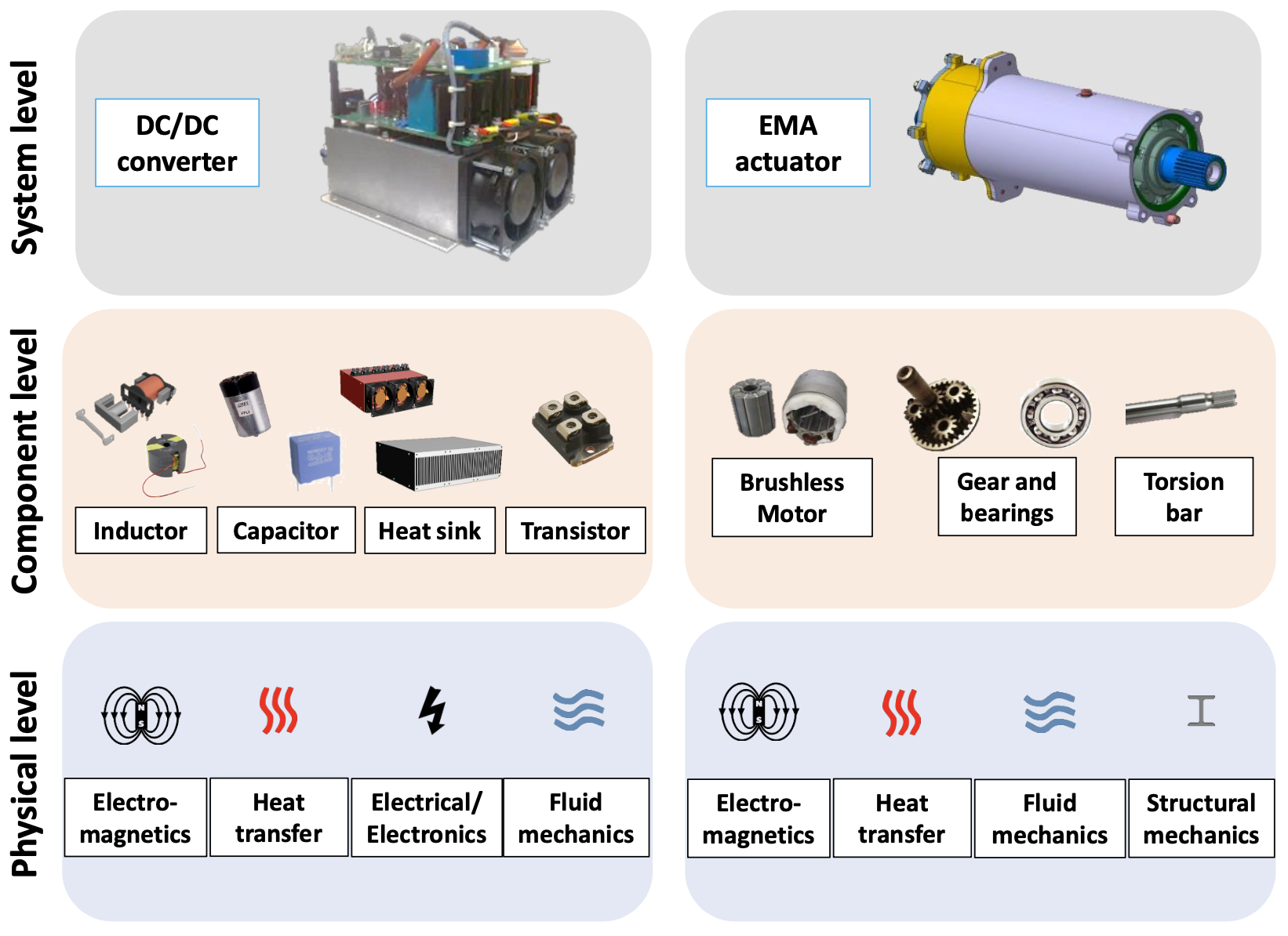
The design and sizing of multiphysics systems requires the ability to understand several levels:
a system level which must make it possible to meet the needs of the application through the interaction of multiple components
a component level which must make it possible to represent the operational and physical limits of the latter.
1.1.3. Designer challenges#
Description
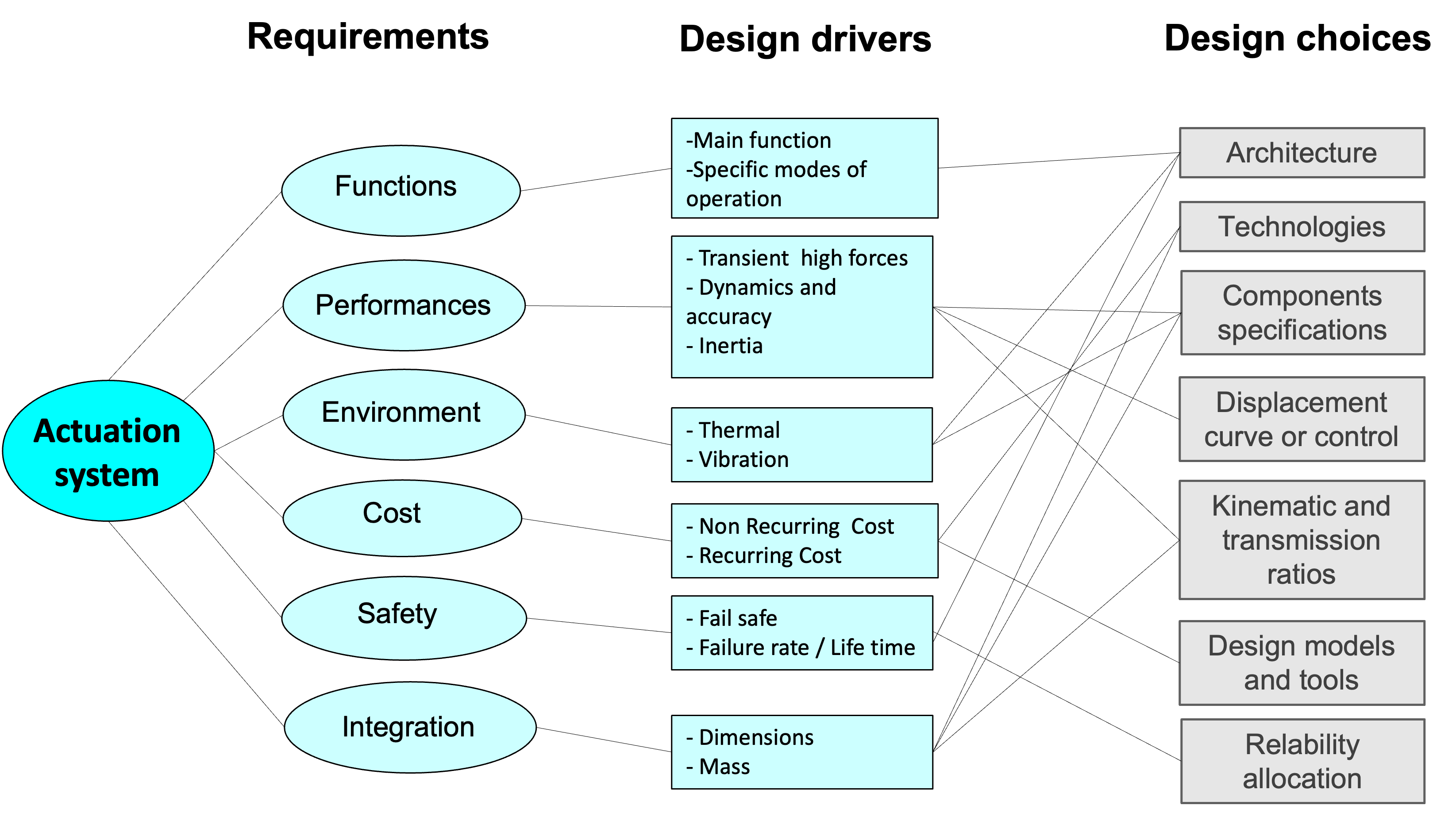
This Figure is a graphic illustration of how classical types of requirements and the key design drivers are associated in an actuation system. Such systems must meet a variety of requirements:
At functional level, multiple operational modes may be requested. In addition to the primary function of positioning in active mode, specific modes can be added for each application: no load standby or passive damping for an aileron control surface, active damping for a TVC, free castering for steering, etc. These functions will require additional specific components or control loops (max speed limitation function of position or flight condition, load limitation, etc.).
At performance level, the requirements may relate to transient or continuous forces, maximum speeds, damping coefficients, accuracy levels, bandwidths, stability coefficients, stiffness or disturbance rejection, etc. These different levels of performance and endurance can also be expressed by typical or critical mission profiles.
At integration level, the requirements may constrain the geometrical envelope or the mass, or define the attachment points. The environmental constraints are also numerous for embedded systems : thermal stress, shocks and vibrations, electromagnetic pollution, humidity levels … The first two points, heat and vibration can have a dramatic effect on electrical components or slender mechanical housings.
At reliability level, a critical system like an aileron must present a fail-safe operation associated with a high rate of reliability for each mode. These requirements may have a significant impact on the complexity of the architecture for power transmission, monitoring or control.
The designer has a panel of degrees of freedom to respond to. The choice of the components, their combination and their technology, i.e. the architecture, provides a first set. The size chosen for the components, the parameters of the kinematic transmission, the shapes of displacement curves, i.e. the sizing, give a second set. The overlaps between these degrees of freedom and requirements are numerous and interconnected. The design of the operating part of a mechatronic system therefore involves a relatively large number of components of different technologies. Each component has specific design drivers to satisfy multiple requirements.
1.1.4. V-model#
Description
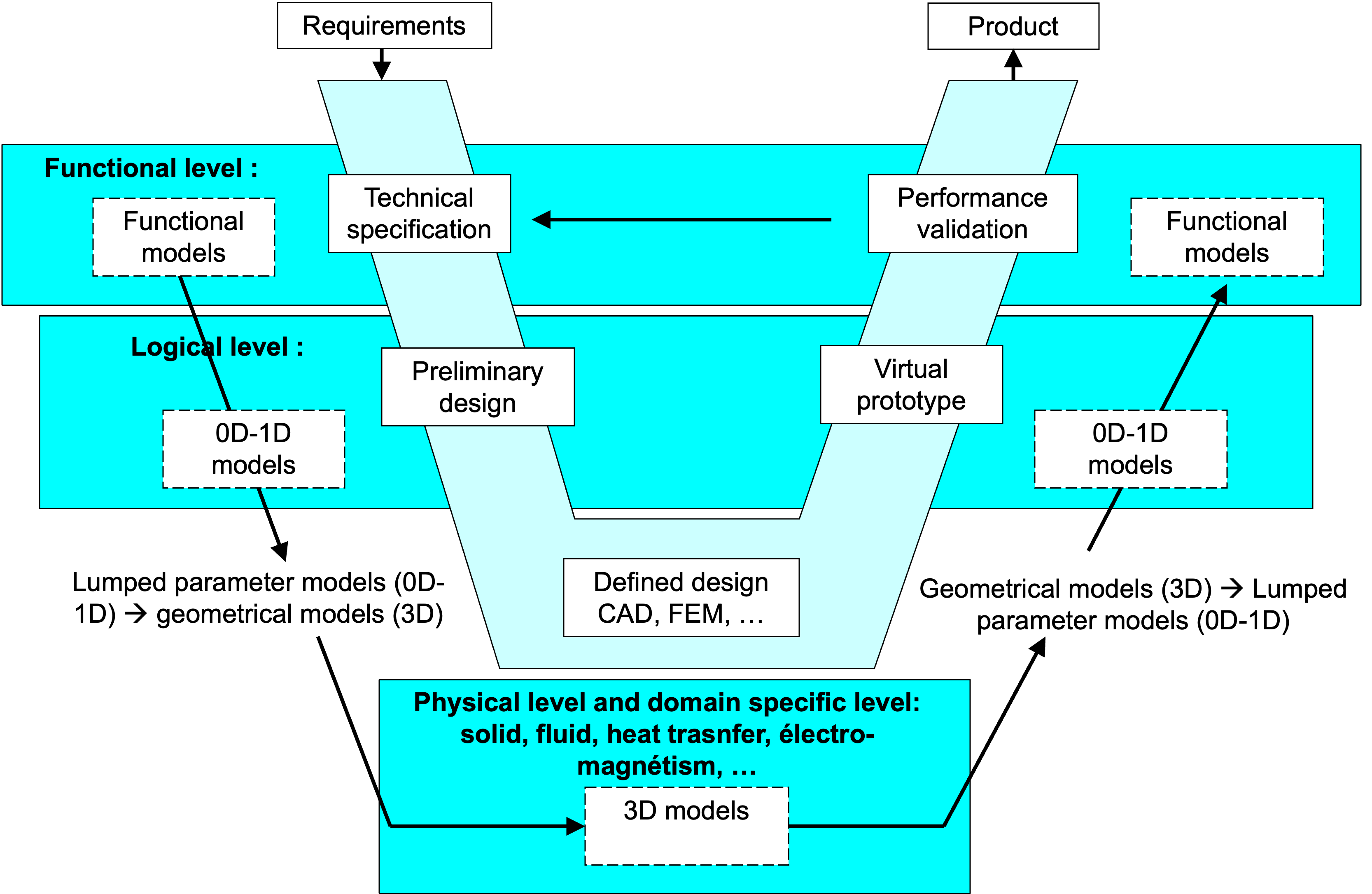
Different types of models are used during the process of developing of a mechatronic system. In the descending phase of the V, the system is gradually defined and the complexity of the models increases accordingly. During the first phase, modeling and simulation are typically used to validate the correctness of the design choices.
First, a functional description of the system to be developed is made using functional simulation models (software tools: UML, SysML, etc.).
In a second step, the “solution concepts” are identified and corresponding physical or behavioural simulation models are developed. These physical models can be static (software tools: Matlab, Mathcad, spreadsheet, etc.) or dynamic (software tools: Matlab / Simulink, Dymola, AMESim, etc.).
During the specific design phase, the various components of the solution concepts are defined in more detail. It is then possible to produce 3D models of these components (software tools: Catia, Abaqus, Flux3D, etc.). These 3D models can perform local computations (finite element) and can thus verify the properties of the developed components more accurately.
Finally, during the system integration phase, the various components are assembled to form the solution concepts and validate their performance. To do this, the highly detailed 3D simulation models, are transformed into less detailed 0D-1D macro-models in order to perform physical simulations.