8.6. Architecture of the converter and sizing scenarios#
Written by Marc Budinger, INSA Toulouse, France
Before sizing a system, it is important to define all the constraints that could have an influence on the design. It is therefore advisable to list meticulously:
the power components to size in the architecture
criteria and parameters useful for the selection of components
system usage scenarios that can “activate” these sizing scenarios
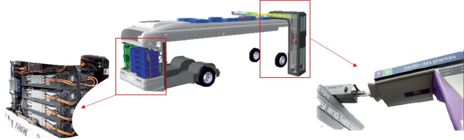
8.6.1. Watt System#
The WATT system includes:
In the bus: a battery pack and a ultra capacitors pack associated with an electric power train, a connection system, an automatic arm, installed on the roof of the vehicle
On the sidewalk: a charging station or “totem” with the connection, as well as a pack of super capacitors, all integrated in the urban landscape.
Each totem (or charging station) is connected to the household electricity distribution network and allows charging between the passage of each bus. There is no need for specific equipment (substation, transformer). In operation the bus is powered by supercapacitors, it travels the necessary distance to the next stop, thanks to the energy stored. At each stop, the arm deploys and realizes in 10 seconds the transfer of energy between the super capacitors of the totem and the super capacitors onboard the bus. An adapted Lithium-ion battery pack is installed in the bus for cases of impossibility of connection and trips without passengers.
Ultracapacitor Pack and Totem
8.6.2. Ultracapacitors modules selection#
In order to estimate the dimensions of the ultracapacities pack, we will be interested in the energy to be supplied to the motorization of the bus on a typical path:
top speed \(v_{max}\) = 30 km/h
distance between 2 totems \(d\) = 800 m
maximum height difference \(h\) = 3 m
The bus has the following characteristics:
mass with passengers \(m\) = 20 t
Rolling coefficient tires \(C_{rr} = 0.01\)
Aerodynamic effect are assume here to be negligeable dur to low speed of the bus.
\(E=E_k+E_g+W_r=1/2*m*v_{max}^2+m*g*h+m*g*C_{rr}*d\)
Exercice: Calculate (with python) the maximum energy to supply (and to store) to the electrical power train.
# Parameters
v_max=30*1000/3600 # [m/s] max speed
m=20e3 # [kg] bus mass
d=800. # [m] distance
h=3. # [m] rise height
C_rr= 0.01 # [-] tyre rolling coef
g=9.81 # [m/s²] gravity acceleration

# Energies & works calculations
E_k=1/2*m*v_max**2 # [J] kinetic energy
E_g=m*h*g # [J] potential gravity energy
W_r=m*g*C_rr*d # [J] friction work of rolling coef
E_t=E_k+E_g+W_r # [J] Total energy for 1 travel

print("Kinetic energy   : %.2g J"%E_k)
print("Potential energy : %.2g J"%E_g)
print("Friction work    : %.2g J"%W_r)
print("Total energy     : %.2g J"%(E_t))
Kinetic energy   : 6.9e+05 J
Potential energy : 5.9e+05 J
Friction work    : 1.6e+06 J
Total energy     : 2.9e+06 J
We will take as ultra-capacitor reference the following module from Maxwell Technologies.
Maxwell module characteristics
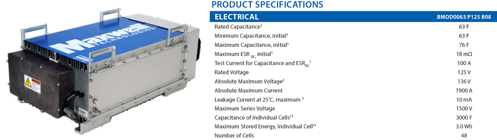
Exercice: Explain and calculate with python the minimum number of modules assuming that the minimum operating voltage will be equal to \(V_{max}/2\).
import math

# Maxwell module characteristics
V_max=125. # [V] Max voltage
C=63. # [F] Module capacitance

# Modules number calculation
V_min=V_max/2
E_1mod=1/2*C*(V_max**2-V_min**2)
N_mod=math.ceil(E_t/E_1mod)

print("Number of 125 V - 63 F modules :",N_mod)
Number of 125 V - 63 F modules : 8
8.6.3. DC/DC converter architecture#
We now assume that each ultracapacity module will be connected to the main DC bus of the bus by a dedicated DC / DC converter. This converter will be responsible for managing the charge and the discharge of the module. The rest of the work will try to size this DC/DC converter. We will represent first here the Work Breakdown Structure of the Watt system (bus) with the equipment (DC/DC converter) to be design.
Remark: following diagrams have been developed with the Mermaid live editor

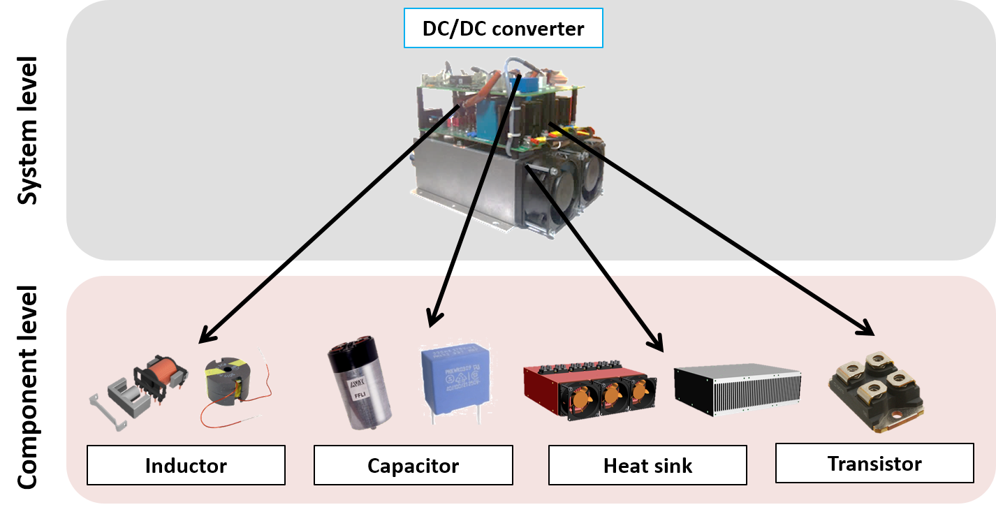
The function of the DC/DC converter is to adapt the voltage between the DC bus and the ultracapacitor module. The following figures illustrates the main components of this converter.
DC/DC converter components
DC/DC converter diagram
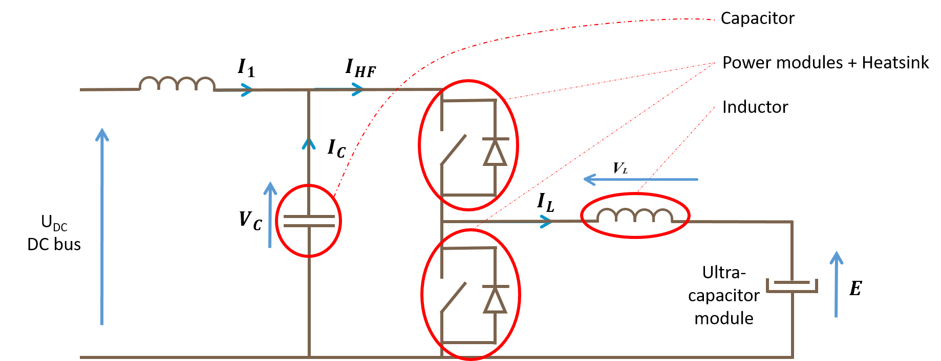
The inductor enables to limit the current ripple in the load (here the ultracapcitor). The capacitor enables to limite the ripple voltage on the DC bus.
8.6.4. Design drivers#
We are going to determine here the possible reasons of the degradation in system’s components. These degration can be:
Fast and come from transient power demands (such as permanent deformation, rupture for mechanical components)
Gradual and come from continuous power demands which often reduce the component’s and therefore the system’s lifetime (such as mechanical fatigue for mechanical components)
The component can also have imperfections which can increase the mechanical stresses on itself or other components. For example, the inertia of a electrical motor increases the torque this same motor has to deliver or can destroy mechanical component when a sudden stop occurs.
We will complete the graph with possible sources of degradation of the components of the DC/DC converter.

8.6.4.1. Sizing scenarios#
We have listed the different degradation risks for our application. Now we have to find the system uses which can create this degradation risks.
Exercice: Propose sizing scenarios for the different DC/DC converter components.